1. Advantages of PLC&inverter control scheme
In many music fountain control systems, whether relay control or solenoid valve is used to control the musical fountain (switch and fountain head control), these methods have weakness of slow response because they cannot regulate the motor or other control valves. Therefore, the focus of this design is on the synchronous real-time nature of music and fountains. In the control system, variable frequency speed control is used, and the inverter is used to control the motor so as to achieve rapid response.
2.1 Song play
The music played by the musical fountain can be played from CD, VCD, DVD and other players. Through the power amplifier, the selected song is divided into two channels, one channel is output to the speaker device, and the other channel is output to the audio converter module to sample the audio signal. . After the operator determines the demo tune in the music database, the driver is then started and the selected tune is played correctly.
2.2 Water type and music synchronization control
When the music starts playing, the water type will be synchronized. During the interval between the end of the previous music and the start of the next music, the water model will also stop at the same time and continue the demonstration. This music fountain control system can provide adjustable fountain delays, so that the water type and music to achieve the effect of synchronization.
2.3 Water type rhythm follow-up control
For different music, the jump and swing of the water type is synchronized with the rhythm of the music, showing the passion and vitality of the musical fountain. This type of jump and swing of the water type is also represented by the corresponding program after the audio converter acquires and converts the audio signal. The frequency converter controls the acceleration and deceleration of the submersible pump so as to achieve different views of different music signals.
2. Music fountain hardware components
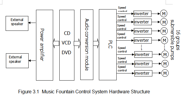
The hardware system is mainly composed of a PLC (a main controller PL80-M44MAD-DC, an expansion module PL80-E4DA2 three), an audio conversion module, a frequency converter, and a submersible pump. The sampling and conversion of the external audio signal by the PLC control the operation of the frequency converter to achieve the requirements of the control system, and can realize the perfect combination of music and fountain in real time. The hardware components of the music fountain control system are shown in Figure 3.1.
3. Control principle
The main circuit diagram of the control system mainly includes inverter and submersible pumps. The power line of the frequency converter is obtained directly from the three-phase AC power and connected to three terminals R, S and T respectively. The corresponding output is to the submersible pump, and the submersible pump is connected to three terminals U, V and W. The control system inverter in the circuit has rich protection functions and can effectively protect the stable operation of the entire system. The frequency changer DI1 is controlled by the DO output of the PLC to start and stop, and AI1 is given by the analog frequency of the PLC. The output of different analog signals changes the speed of the submersible pump. The specific circuit diagram of the control system is shown in Figure 4.1.
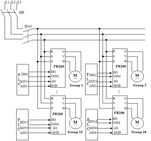
Figure 4.1 Main circuit diagram of the control system
Inverter main parameter settings:
F01.01 | Master Frequency Command Source | 2 | Analog input AI1 |
F02.00 | Run command | 1 | Terminal Control |
F03.00 | Accel time 1 | 5 | Adjust according to the actual situation in the field |
F03.01 | Decel time 1 | 5 | Adjust according to the actual situation in the field |
F04.00 | Function of terminal DI1 | 1 | Running forward (FWD) |
The speed regulation of the inverter is only given by the external PLC signal, and various speeds can be output through the analog quantity. Even when the inverter is running, various speeds (frequencies) can be arbitrarily set in the range of 0 to 60 Hz.
4. PLC software control section
5.1 Main program flow chart
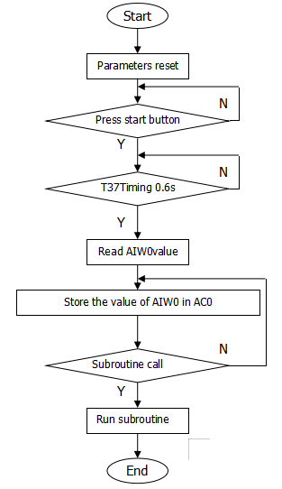
As shown in Figure 5.1, when the PLC is running, the PLC starts parameter initialization and starts scanning the system program. When the start button is pressed, the system main program will perform the following steps: Start timing Every s reads the value in AIW0. The stored value is stored in the accumulator AC0, AC0 is compared with the internal set value, and then it is determined which subroutine is specifically called. After the selection, the subroutine is run and the routine ends.
5.2 Stopped flow chart
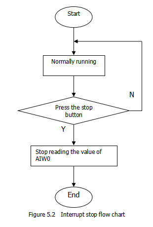
When the system needs to be shut down, no matter what the situation is, you can press the stop button directly, and the PLC will stop all work. Figure 5.2
 As shown.
