

The integration ofresidential energy storage systems addresses the growing necessity for localized battery backup and energy stability.
A power inverter serves as the central conversion hub in these systems, transforming stored Direct Current (DC) battery power into usable Alternating Current (AC) power for standard household appliances. Operating a solar power inverter for home use involves accurate technical planning, load calculation, and adherence to specific electrical safety protocols.
System Planning and Accurate Load Sizing
Accurate load calculation relies on balancing the inverter’s capacity with continuous running watts and initial motor startup surges. Selecting the correct waveform and DC voltage establishes a stable energy foundation.
Continuous vs. Surge Power
Understanding the distinction between continuous and surge power prevents inverter shutdown or damage:
l Continuous Power (Running Watts): The maximum wattage an inverter can deliver steadily during normal, ongoing operation.
l Surge Power (Starting Watts / Peak Power): A brief burst of elevated wattage, typically lasting 1 to 2 seconds, that an inverter can handle during initial equipment startup.
Devices equipped with electric motors or compressors draw an inductive startup surge 3 to 6 times higher than their normal running watts. If the inverter cannot supply this initial burst, it trips or shuts down, even if the total running wattage is well within normal operating limits.
Appliance Load Calculations
When auditing electrical loads, appliances generally fall into motor/inductive loads or resistive/electronic loads:
Appliance | Running Watts | Surge Multiplier / Surge Watts |
Refrigerator / Freezer | 150–400 W | 3–5x (800–1,200 W) |
Solar / Central AC (1 ton / 15k BTU) | 900–1,500 W | 3–4x (2,500–4,000 W) |
Well Pump / Water Pump (1 HP) | 750–1,500 W | 3–4x (2,500–3,500 W) |
Microwave | 800–1,500 W | 1.5x (1,200–2,000 W) |
Power Tools / Drills | 500–1,000 W | 2–3x (1,500–2,500 W) |
Laptops / LED TVs / LED Lights | 8–150 W | Minimal to None |
Step-by-Step Load Sizing Calculation
Sizing an inverter system accurately follows a four-step engineering framework:
1. Calculate Simultaneous Continuous Load: List all devices intended to run at the same time and sum their continuous/running wattages (calculated as Watts = Volts × Amps kVA).
2. Determine Peak Startup Surge: Identify the largest single surge requirement among motor-driven devices to establish the minimum inverter surge capability.
3. Add a Safety Margin (20–25%): Multiply the simultaneous continuous wattage by 1.2 to 1.25. This buffer protects the system from unexpected demand spikes, thermal derating, and internal conversion losses.
Ø Example: If the simultaneous running load totals 1,345 W with a highest single surge load of 1,200 W, applying a 25% safety margin yields 1345 × 1.25 = 1681W. Therefore, a 2,000 W continuous / 2,000 W+ surge inverter will be right for you.
4. System Architecture Matching:
l Solar String Inverters: Size the inverter capacity at 80% to 110% of the total solar array wattage.
l DC Battery Voltage Selection: Small setups under 3 kW typically operate on 12V or 24V banks; larger systems (3 kW to 10 kW+) use 24V or 48V to reduce current draw, cable thickness, and voltage drop.
Waveform Selection
The quality of the AC output waveform dictates which equipment can safely run on the system:
Pure Sine Wave:
l Characteristics: Delivers clean AC electricity identical to utility grid power.
l Applications: Essential for solar installations, sensitive electronics, variable-speed drives, solar air conditioners, refrigerators, and medical equipment.
l Efficiency: Optimal efficiency with no derating required; motors run cooler, quieter, and last longer.
Modified Sine Wave:
l Characteristics: Produces a choppy, stepped approximation of a sine wave.
l Applications: Acceptable only for basic resistive heating elements or simple tools.
l Limitations: Motors operate 10–20% less efficiently, run hotter, and can suffer premature component wear; can disrupt or damage sensitive electronics, chargers, and variable-speed compressors.
Square Wave:
l Characteristics: Rough square wave output.
l Limitations: Not recommended for modern electronic devices.
Battery Bank Configuration and DC Parameters
An inverter relies entirely on the stability of its DC power source. Aligning input voltages, selecting appropriate battery chemistry, and sizing cables correctly ensures sustained energy delivery without premature cell degradation.
System Voltage Selection and Wiring Topologies
Matching the battery bank voltage to the inverter's rated input voltage is required for safe operation. Target system voltage scales with total power demand:
l Small Systems (< 3 kW): Operate on 12V or 24V DC.
l Medium Systems (3 kW – 10 kW): Operate on 24V or 48V DC.
l Large Systems (10 kW+): Require 48V DC or higher.
Increasing system voltage reduces the current draw (Amperage) for the exact same power output. Lower amperage drastically reduces I2R resistive heat losses, improves overall conversion efficiency, and permits the use of thinner DC cables.
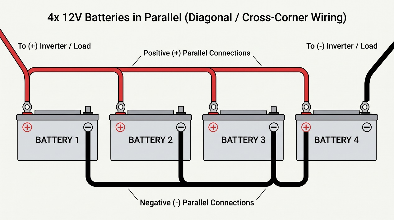
Batteries are configured in distinct topologies to achieve target voltages and runtimes:
l Series Wiring (Increases Voltage): Connects the positive terminal of one battery to the negative terminal of the next. Wiring two 12V batteries in series creates a 24V bank while the Amp-hour (Ah) capacity remains unchanged.
l Parallel Wiring (Increases Capacity): Connects all positive terminals together and all negative terminals together. Wiring two 100Ah 12V batteries in parallel creates a 200Ah bank at 12V.
l Series-Parallel: Combines both methods to build higher-voltage, high-capacity banks.
Safe configuration requires pair-matching batteries within a bank. All batteries share identical brand, age, capacity, and State of Charge (SoC). Mixing old and new batteries or different chemistries leads to rapid bank failure.
Battery Chemistry and Discharge Thresholds
Chemistry dictates the bank's usable capacity, cycle life, and lifetime economics. Inverters and charge controllers are programmed with specific low-voltage cutoffs to prevent cell damage.
Parameter | LiFePO4 (Lithium Iron Phosphate) | AGM (Absorbent Glass Mat) | Flooded Lead-Acid |
Usable Depth-of-Discharge (DoD) | 100% usable (Maintained with a 20% SoC buffer) | 50% limit (200Ah delivers 100Ah) | 50% limit |
Cycle Life | 3,000–6,000 cycles | 500–800 cycles | 500–800 cycles |
Lifespan | 8–15 years | 5–7 years | 5–7 years |
Weight | ~1/3 weight of AGM | Heavy | Heavy |
Maintenance & Features | Built-in BMS protection; requires lithium charging profile | Sealed, maintenance-free | Requires monthly water top-ups & ventilation |
Discharging lead-acid batteries (AGM and Flooded) beyond a 50% State of Charge causes premature capacity loss. Lithium chemistries (LiFePO4) support 80% to 100% usable DoD, though a 20% SoC cutoff is standard to maximize cycle life.
DC vs. AC Amperage Math and Cable Sizing
Household appliances draw power at standard AC line voltage (120V or 240V AC), whereas the inverter pulls current from a low-voltage DC battery bank. This voltage difference means DC current is dramatically higher than AC current.
l AC Amperage Formula: 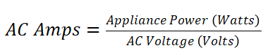
l DC Amperage Formula: 
A comparison of a 2,000 W AC load across different battery banks illustrates the impact on cabling and efficiency:
l 12V DC Bank: Draws about 167 A DC. Requires 4/0 AWG cables; delivers 85–90% system efficiency.
l 24V DC Bank: Draws about 83 A DC. Requires 2/0 AWG cables; delivers 90–93% efficiency.
l 48V DC Bank: Draws about 42 A DC. Requires 2 AWG cables; delivers 93–96% efficiency.
Attempting to run a 5,000 W load on a 12V system pulls over 400 Amps DC, demanding extreme cabling infrastructure (such as 350 MCM or double 4/0 AWG wire) and introducing severe thermal stress.
Safety Standards, Wiring, and Thermal Management
High-amperage electrical systems require strict environmental controls and regulatory compliance. Managing ambient temperatures, integrating proper DC fusing, and adhering to global standards prevents thermal hazards and hardware failure.
Global Regulatory Compliance and Safety Standards
Power inverter standards are formalized regulations defining electrical safety, operational performance, and electromagnetic compatibility (EMC) requirements to prevent fires, electrical shock, and utility conflicts.
Rigorous standardized testing reduces inverter-related safety incidents by over 80%, whereas uncertified units carry 3 times higher rates of component failure and electrical fires.
Key global and regional standards governing inverter deployment include:
l UL 1741 / UL 1741 SA (North America): Governs electrical safety, grid interconnection, anti-islanding protection, and cybersecurity protocols for smart grid-connected units.
l IEC 62116 & IEC 62093 (Global): IEC 62116 mandates anti-islanding protection and fault-response times for utility-scale setups, while IEC 62093 defines environmental durability testing for off-grid renewable energy hardware.
l EN 50530 / EN 62116 / EN 61000 (European Union): Establishes minimum efficiency thresholds, low-voltage safety rules, and EMC limits for grid-connected systems. FRECON equipment maintains strict compliance with European CE safety standards.
l AS/NZS 4777.2 (Australia & New Zealand): Regulates grid voltage management and interconnection rules for inverter-integrated battery storage.
l GB/T 37408 (China): Defines PV inverter safety, power quality, and grid-support capabilities.
Safety standards isolate physical hazards through strict insulation and grounding benchmarks, whereas performance standards establish metrics for efficiency and total harmonic distortion.
To protect against counterfeit certification marks, present on roughly 8% of uncertified market units, installers are advised to check product labels, demand third-party test reports, and cross-reference certification numbers against public regulatory databases.
Thermal Management and Environmental Controls
Inverters generate internal thermal energy while chopping DC into AC across high-frequency MOSFET or IGBT switches. Unmanaged heat is the leading driver of component degradation, specifically shortening the lifespan of internal electrolytic capacitors.
High ambient temperatures diminish maximum continuous output power through thermal derating. For example, a 3,000 W inverter can be thermally derated to deliver only 2,400 W at 104°F (40°C). As an engineering benchmark, every 18°F (10°C) increase in operating temperature degrades inverter conversion efficiency by roughly 1%.FRECON industrial models are engineered to operate within a wide temperature range of -25°C to 60°C.
Cooling architectures utilize passive heat sinks or active variable-speed cooling fans to dissipate heat. Specialized units designed for extreme climates incorporate IP65 or IP66 weather and dust ingress protection, preventing thermal capacity derating even at ambient temperatures exceeding 50°C (122°F).
Proper installation and maintenance require:
l Mounting the unit in a dry, well-ventilated space protected from direct sunlight, high humidity, and dust accumulation.
l Maintaining generous clearance around heat sink fins and chassis vents (typically a minimum of 6 inches).
l Cleaning dust and debris from cooling fans and heat sinks every 3 to 6 months to avoid thermal overload alarms. Advanced AI-equipped inverters actively track thermal profiles to generate predictive maintenance alerts prior to fan failure or heat-induced shutdown.
Conclusion
Establishing a reliable home backup power system depends on accurate load calculations, compatible battery chemistries, and effective thermal management. FRECON SP500 and SP520 Off-Grid Solar Inverters span a power capacity range from 1.2 kW to 5.5 kW.
These pure sine wave units feature integrated MPPT controllers with operating voltage ranges up to 120–450 VDC on high-voltage variants. Additionally, they include standard BMS communication interfaces and support battery-free operation. Refer to FRECON technical datasheets or contact our engineering team for detailed integration dimensions and electrical specifications.